
Source Description:
Dimensions for the Med3633 source 1, 2 are taken from the TG43 2004 update (Rivard et al) 1 and Li et al's 2 study. The Med3633 103Pd seed consist of two polystyrene spheres of 0.50 mm diameter as described in TG-43U1 1 report (Note; The prevoius database used a diameter of 0.56 mm consistent with an earlier Rivard study 3) The spheres are coated with a negligible thickness of radioactive material, located on either side of two 0.50 mm diameter 80.0% gold/ 20.0% copper alloy spheres. The encapsulating titanium cylinder has an outer diameter of 0.80 mm and an inner diameter of 0.710 mm (Note; The prevoius database used 0.81 mm diamater consistent with the Rivard study 3). The source has an average weld thickness of 0.10 mm. Calculations are done with the internal spheres arranged in the "ideal" configuration (center of source spheres located at ± 1.807 mm and ± 1.084 mm, center of marker spheres located at ± 0.361 mm) given in the study of the Med3631 125I seed by Rivard 3. Rivard's study of the Med3631 also contains a discussion on how the internal movement of the source spheres effects dosimetry parameters but this is not taken into account here. The overall length is 4.70 mm and the active length is assumed to be 4.20 mm. Li et al 2 and Wallace et al 4 studies of the Med3633 source took the overall source lenght as 4.5 mm, with inner and outer diammeter of 0.70 and 0.80 mm. The mean photon energy calculated on the surface of the source is 20.50 keV with mean statistical uncertainties < 0.01% .
Dose-Rate Constant - Λ :
Dose-rate constants, Λ , are calculated by dividing the dose to water per history in a (0.1 mm)3 voxel centered on the reference position, (1 cm,Π/2), in a 30x30x30 cm3 water phantom, by the air-kerma strength per history (scored in vacuo). As described in ref. 5, dose-rate constants are provided for air-kerma strength calculated using voxels of 2.66x2.66x0.05 cm3 (WAFAC) and 0.1x0.1x0.05 cm3 (point) located 10 cm from the source. The larger voxel size averages the air-kerma per history over a region covering roughly the same solid angle subtended by the primary collimator of the NIST WAFAC 6,7 used for calibrating low-energy brachytherapy sources and is likely the most clinically relevant value. The small voxel serves to estimate the air-kerma per history at a point on the transverse axis and includes a small 1/r2 correction (0.5%)5. egs_brachy and BrachyDose MC uncertainties are statistical uncertainties only (k=1).
| Author | Method | Λ (cGy h-1 U-1) | Abs. Uncertainty |
| Safigholi et al 8 | WAFAC | 0.6632 | 0.0001 |
| Safigholi et al 8 | point | 0.6616 | 0.0013 |
| Taylor, Rogers 9 | WAFAC | 0.650 | 0.002 |
| Taylor, Rogers 9 | point | 0.650 | 0.002 |
| Rivard 10 | MCNP (extrap) | 0.672 | --- |
| Wallace, Fan 4 | TLD | 0.68 | 0.033 |
| Li et al 2 | MCPT (extrap) | 0.677 | --- |
| Li et al 2 | Diode | 0.682 | --- |
| Rodriguez, Rogers 11 | TLD (Revised Wallace) | 0.675 | 0.036 |
| Rodriguez, Rogers 11 | BrachyDose (WAFAC) | 0.665* | 0.002 |
| Rivard et al 1 | Consensus Value | 0.688 | --- |
*The DRC values from Taylor-Rogers9 differ from those here and in Rodriguez-Rogers11 due to some geomtry improvements with BrachyDose by Rodriguez-Rogers.
Radial dose function - g(r):
The radial dose function, g(r), is calculated using both line and point source geometry functions and tabulated at 36 different radial distances ranging from 0.05 cm to 10 cm. Fit parameters for a modified polynomial expression are also provided 12 . The mean residual deviations from the actual data for the best fit were < 0.10%.

| Fitting coefficients for g L (r) = (a0 r-2 + a1 r-1 + a2 + a3r + a4r2 + a5 r3) e-a6r | |||
| Fit range | Coefficients | ||
| r min (cm) | r max (cm) | ||
| 0.1 | 10.00 | a0 / cm2 | (2.53+/-0.04)E-03 |
| a1 / cm | (-1.328+/-0.006)E-01 | ||
| a2 | (1.8896+/-0.0024)E+00 | ||
| a3 / cm-1 | (7.4+/-0.8)E-02 | ||
| a4 / cm-2 | (-2.98+/-0.06)E-02 | ||
| a5 / cm-3 | (2.18+/-0.04)E-03 | ||
| a6 / cm-1 | (5.925+/-0.034)E-01 | ||
Anisotropy function - F(r,θ):
Anisotropy functions are calculated using the line source approximation and tabulated at radii of 0.1, 0.15, 0.25, 0.5, 0.75, 1, 2, 3, 4, 5, 7.5 and 10 cm and 32 unique polar angles with a minimum resolution of 5°. The anisotropy factor, φan (r), was calculated by integrating the solid angle weighted dose rate over 0° ≤ ϑ ≤ 90°.
F(0.25,θ) 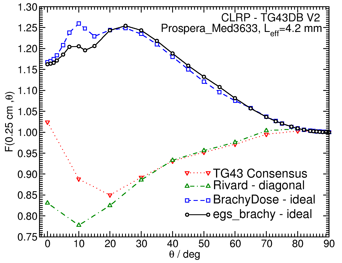 |
F(0.50,θ) 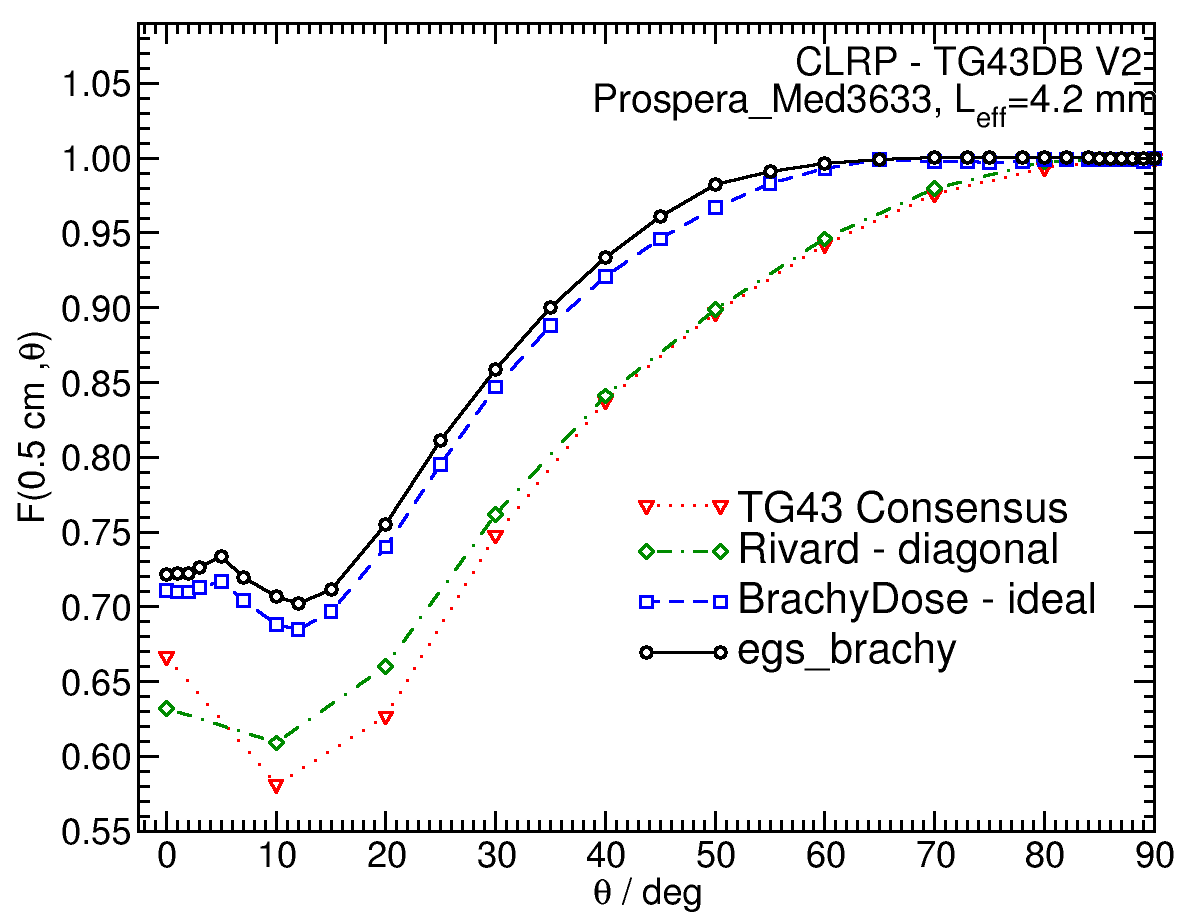 |
F(1.00,θ) 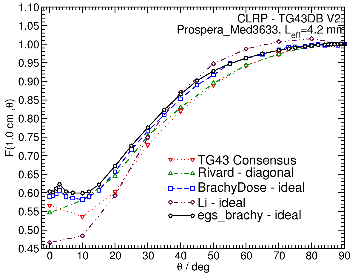 |
F(5.00,θ) 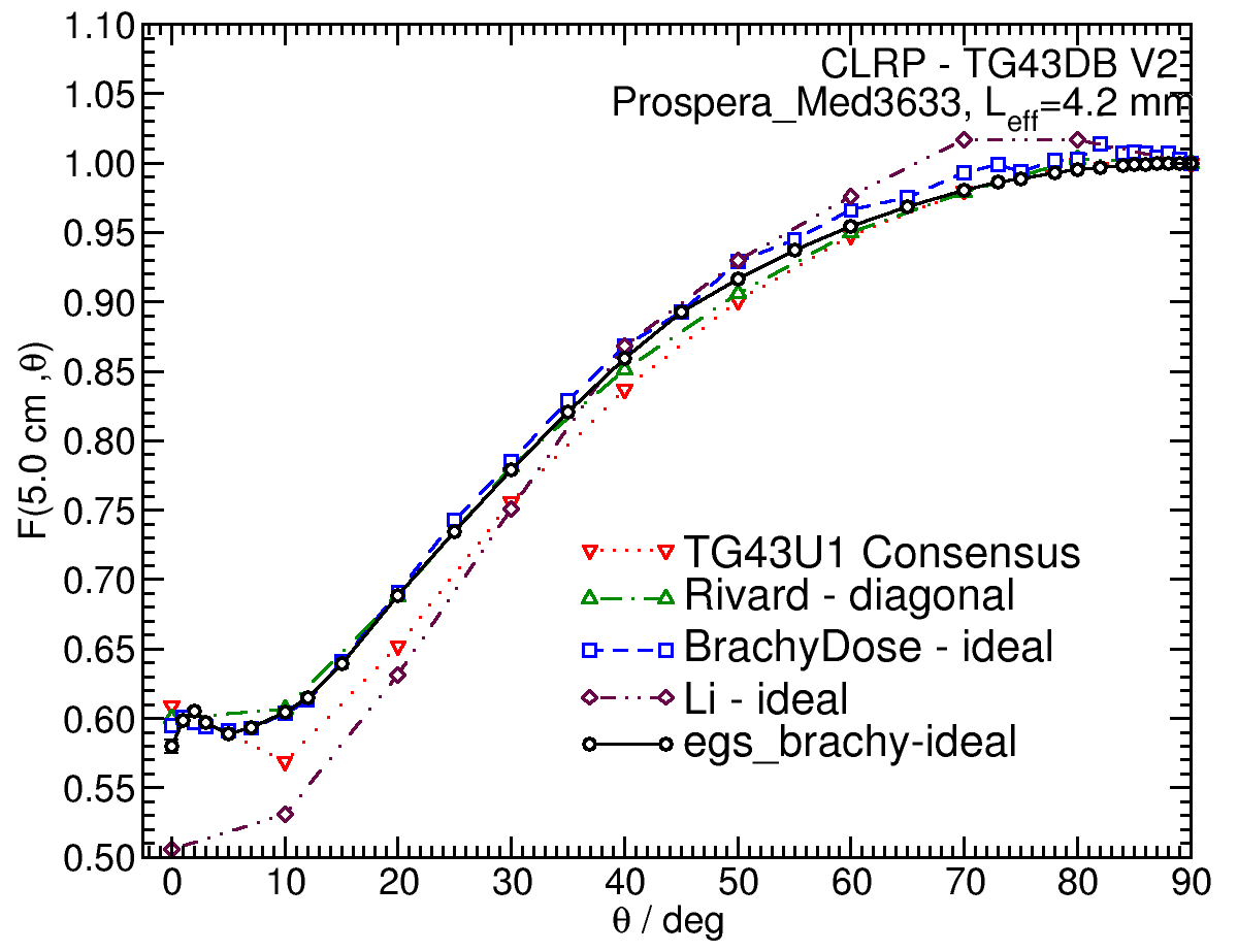 |
Tabulated data:
Tabulated data are available in .xlsx format: Excel
References:
1. M. J. Rivard et al , Update of AAPM Task Group No. 43 Report: A revised AAPM protocol for brachytherapy dose calculations, Med. Phys.,31, 633 - 674, 2004.
2. Z. Li et al , Monte Carlo caculations and experimental measurements of dosimetry parameters of a new 103Pd source, Med. Phys., 27 , 1108-1112, 2000. 3. M J Rivard, Monte Carlo calculations of AAPM Task Group Report No. 43 dosimetry parameters for the MED3631-A/M 125I source, Med. Phys., 28 , 629-637, 2001 4. R. E. Wallace, J. J. Fan, Report on the dosimetry of a new design 125 Iodine brachytherapy source, Med. Phys., 26 , 1925-1931, 1999. 5. R. E. P. Taylor et al , Benchmarking BrachyDose: voxel-based EGSnrc Monte Carlo calculations of TG-43 dosimetry parameters, Med. Phys., 34 , 445 - 457, 2007. 6. R. Loevinger, Wide-angle free-air chamber for calibration of low-energy brachytherapy sources, Med. Phys., 20 , 907, 1993
7. S. M Seltzer et al , New National Air-Kerma-Strength Standards for 125I and 103Pd Brachytherapy Seeds, J. Res. Natl. Inst. Stand. Technol.,108, 337 - 358, 2003.
8. H. Safigholi, M. J. P. Chamberland, R. E. P. Taylor, C. H. Allen, M. P. Martinov, D. W. O. Rogers, and R. M. Thomson, Updated of the CLRP TG-43 parameter database for LDR low-energy brachytherapy sources, to be published (Current calculation). 9. R. E. P. Taylor, D. W. O. Rogers, An EGSnrc Monte Carlo-calculated database of TG-43 parameters, Med. Phys., 35 , 4228-4241, 2008.
10. M J Rivard, A discretized approach to determining TG-43 brachytherapy dosimetry parameters: case study using Monte Carlo calculations for the MED3633 103Pd source, Appl. Radiat. Isotopes, 55,775-782, 2001.
11. M. Rodriguez , D. W. O. Rogers, Effect of improved TLD dosimetry on the determination of dose rate constants for 125I and 103Pd brachytherapyseeds,Med.Phys.41, 114301-15, 2014. 12. R. E. P. Taylor, D. W. O. Rogers, More accurate fitting of 125I and 103Pd radial dose functions, Med. Phys., 35 , 4242-4250, 2008.