Source Description:
Dimensions for the 6733 seed 1,2 are taken from the study by Sowards et al 1 and Meigooni 2. The 6733 source consists of 125I coated on a 3.0 mm long cylindrical silver rod which is 0.25 mm in diameter. In this study the 125I coating is assumed to have a thickness of 10.0 μm on both the cylindrical surface and end faces (Note: in the v1 version of this database, the coating layer was assumed to have a thickness of 2.0 μm). The silver rod is encapsulated in a titanium tube with 0.050 mm thick walls, 0.80 mm outer diameter and 0.50 mm thick end welds. End welds are modelled using a 0.40 mm Ti hemisphere overlapped with a 0.350 mm air sphere with its center shifted by 0.250 mm relative to the Ti sphere. The titanium casing is unique in that it is "threaded" with 6 threads. In this study the threads are taken to be a series of eleven 0.050 mm thick cylindrical shells each approximately 0.332 mm wide and spaced evenly over the central 3.0 mm of the seed. To create the threads, every other cylindrical shell is indented 0.250 mm from the outer cylinders (i.e. the inner threads have inner and outer radii of 0.325 mm and 0.375 mm, respectively). The overall source length is 4.50 mm and the active length is 3.0 mm. The cylindrical source element is free to move from the nominal position by approximately 0.40 mm along the seed axis and 0.065 mm in the radial direction, however, we assume it is always centred. The mean photon energy calculated on the surface of the source is 27.29 keV with statistical uncertainties < 0.014%.
(Note: With a 2.0 μm rather than 10.0 μm coating layer, differences up to 17% were observed at angles < 20° for 2D anisotropy function between previous database (CLRPv1) , and current update (CLRPv2) or Meigooni et al 1. However, the differences drop to 5% when the iodine coating layer is increased to 10.0 μm.
Dose-Rate Constant - Λ :
Dose-rate constants, Λ , are calculated by dividing the dose to water per history in a (0.1 mm)3 voxel centered on the reference position, (1 cm,Π/2), in a 30x30x30 cm3 water phantom, by the air-kerma strength per history (scored in vacuo). As described in ref. 3 , dose-rate constants are provided for air-kerma strength calculated using voxels of 2.66x2.66x0.05 cm3 (WAFAC) and 0.1x0.1x0.05 cm3 (point) located 10 cm from the source. The larger voxel size averages the air kerma per history over a region covering roughly the same solid angle subtended by the primary collimator of the WAFAC 4,5 at NIST used for calibrating low-energy brachytherapy sources and is likely the most clinically relevant value. The small voxel serves to estimate the air kerma per history at a point on the transverse axis and includes a small 1/r2 correction (0.5%)3. MC uncertainties are only statistical uncertainties (k=1).
| Author | Method | Λ (cGy h-1 U-1) | Abs. Uncertainty |
| Safigholi et al 6 | WAFAC + | 0.9349 | 0.0001 |
| Safigholi et al 6 | point + | 0.9493 | 0.0022 |
| Safigholi et al 6 | WAFAC * | 0.9272 | 0.0001 |
| Safigholi et al 6 | point * | 0.9531 | 0.0023 |
| Taylor, Rogers 7 | WAFAC * | 0.929 | 0.002 |
| Taylor, Rogers 7 | point * | 0.947 | 0.003 |
| Sowards, Meigooni 1 | point (PTRAN) | 0.97 | 0.03 |
| Meigooni et al 2 | TLD | 0.99 | 0.08 |
| Rodriguez, Rogers 8 | TLD (Revised meigooni) | 0.913 | 0.058 |
| Rodriguez, Rogers 8 | WAFAC (BrachyDose) | 0.934 | 0.015 |
| Rivard et al 9 | TG43U1S1 Consensus Value | 0.980 | ---- |
Radial dose function - g(r):
The radial dose function, g(r), is calculated using both line and point source geometry functions and tabulated at 36 different radial distances ranging from 0.05 cm to 10 cm. Fit parameters for a modified polynomial expression are also provided 10 . The mean residual deviations from the actual data for the best fit were < 0.15%.
Click image for higher res version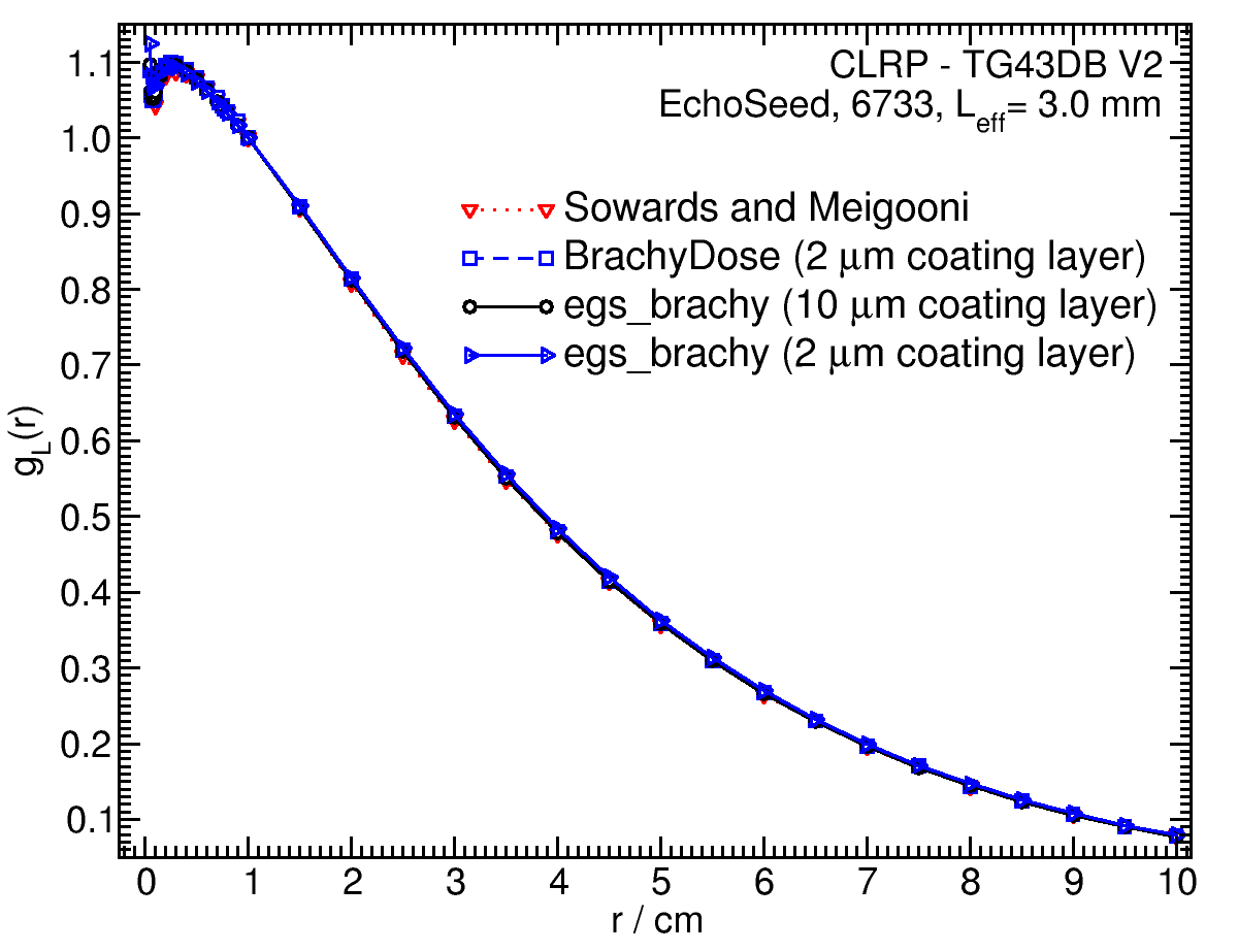
| Fitting coefficients for g L (r) = (a0 r-2 + a1 r-1 + a2 + a3r + a4r2 + a5 r3) e-a6r | |||
| Fit range | Coefficients | ||
| r min (cm) | r max (cm) | ||
| 0.05 | 10.00 | a0 / cm2 | (6.88+/-0.15)E-04 |
| a1 / cm | (-1.862+/-0.034)E-02 | ||
| a2 | (1.1835+/-0.0018)E+00 | ||
| a3 / cm-1 | (3.63+/-0.09)E-01 | ||
| a4 / cm-2 | (-9.1+/-1.3)E-03 | ||
| a5 / cm-3 | (1.27+/-0.09)E-03 | ||
| a6 / cm-1 | (4.20+/-0.06)E-01 | ||
Anisotropy function - F(r,θ):
Anisotropy functions are calculated using the line source approximation and tabulated at radii of 0.1, 0.15, 0.25, 0.5, 0.75, 1, 2, 3, 4, 5, 7.5 and 10 cm and 32 unique polar angles with a minimum resolution of 5 o . The anisotropy factor, φ an (r), was calculated by integrating the solid angle weighted dose rate over 0 o ≤ ϑ ≤ 90 o .
F(1.00,θ) 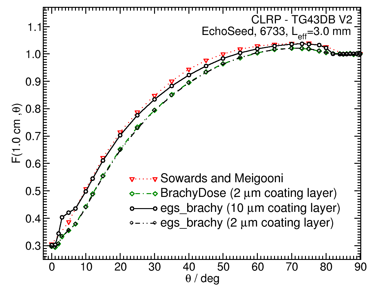 |
F(5.00,θ) 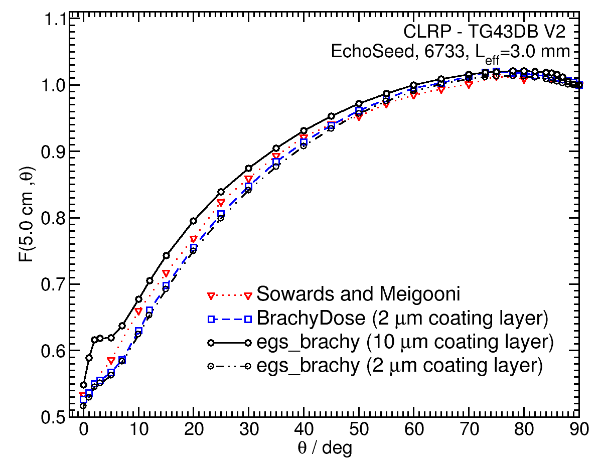 |
References:
1. K. Sowards, A. S. Meigooni, A Monte Carlo evaluation of the dosimetric characteristics of the EchoSeed Model 6733 125I brachytherapy source, Brachytherapy, 1 , 227-232, 2002.
2. A. S. Meigooni et al, Experimental determination of the TG-43 dosimetric characteristics of EchoSeed model 6733 125I brachytherapy source, Med. Phys., 29 , 939-942, 2002.
3. R. E. P. Taylor et al, Benchmarking BrachyDose: voxel-based EGSnrc Monte Carlo calculations of TG--43 dosimetry parameters, Med. Phys., 34 , 445 - 457, 2007.
4. R. Loevinger, Wide-angle free-air chamber for calibration of low--energy brachytherapy sources, Med. Phys., 20 , 907, 1993.
5. S. M Seltzer et al, New National Air-Kerma-Strength Standards for 125I and 103Pd Brachytherapy Seeds, J. Res. Natl. Inst. Stand. Technol., 108 , 337 - 358, 2003.
6. H. Safigholi, M. J. P. Chamberland, R. E. P. Taylor, C. H. Allen, M. P. Martinov, D. W. O. Rogers, and R. M. Thomson, Updated of the CLRP TG-43 parameter database for low-energy photon-emitting brachytherapy sources, to be published (Current calculation).
7. R. E. P. Taylor, D. W. O. Rogers, An EGSnrc Monte Carlo-calculated database of TG-43 parameters, Med. Phys., 35 , 4228-4241, 2008.
8. M. Rodriguez , D. W. O. Rogers, Effect of improved TLD dosimetry on the determination of dose rate constants for 125I and 103Pd brachytherapyseeds, Med.Phys. 41, 114301-15, 2014. 9. M. J. Rivard et al, Supplement to the 2004 update of the AAPM Task Group No. 43 Report, Med. Phys., 34 , 2187 - 2205, 2007.
10. R. E. P. Taylor, D. W. O. Rogers, More accurate fitting of 125I and 103Pd radial dose functions, Med. Phys., 35 , 4242-4250, 2008.