Source Description:
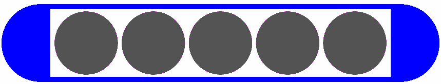
Dimensions given in the paper by Gearheart et al 1 and Nath et al 2 are used for the Imagyn source 1,2,3,4,5 . The Imagyn source consists of five silver spheres, each with a diameter of 0.650 mm (Note: 0.640 mm in CLRPv1 database), coated with 1 μm thickness of AgI and encapsulated in a titanium tube with 0.50 mm thick hemi-spherical end welds (Note: In CLRPv1 database the AgI coating layer was assumed to have negligible thickness). The end welds are modelled as 0.40 mm hemispheres on top of solid cylinders that have a 0.40 mm radius and are 0.10 mm thick. The center of the silver marker spheres are along the seed axis offset 0.690 mm from each other. The tube has 0.050 mm thick walls and an outer diameter of 0.80 mm. The unoccupied space in the source is assumed to be air. The overall length is 4.50 mm and the active length is 3.40 mm. The maximum possible displacement of a source sphere is 0.350 mm along the seed axis as well as up to 0.030 mm in the radial direction. The mean photon energy calculated on the surface of the source is 27.20 keV with statistical uncertainties < 0.003%.Dose-Rate Constant - Λ :
Dose-rate constants, Λ , are calculated by dividing the dose to water per history in a (0.1 mm)3 voxel centered on the reference position, (1 cm,Π/2), in the 30x30x30 cm3 water phantom, by the air-kerma strength per history (scored in vacuo). As described in ref. 5 , dose-rate constants are provided for air-kerma strength calculated using voxels of 2.66x2.66x0.05 cm3 (WAFAC) and 0.1x0.1x0.05 cm3 (point) located 10 cm from the source. The larger voxel size averages the air-kerma per history over a region covering roughly the same solid angle subtended by the primary collimator of the WAFAC 6,7 at NIST used for calibrating low-energy brachytherapy sources and is likely the most clinically relevant value. The small voxel serves to estimate the air kerma per history at a point on the transverse axis and includes a small 1/r2 correction (0.5%) 5. MC uncertainties are only statistical uncertainties (k=1).
| Author | Method | Λ (cGy h-1 U-1) | Abs. Uncertainty |
| Safigholi et al 8 | WAFAC | 0.921 | 0.0001 |
| Safigholi et al 8 | point | 0.922 | 0.0020 |
| Taylor, Rogers 5 | WAFAC | 0.924 | 0.003 |
| Taylor, Rogers 5 | point | 0.923 | 0.003 |
| Ibbott 4 | point (PTRAN) | 0.92 | --- |
| Ibbott, Nath 3 | TLD | 0.92 | 0.07 |
| Nath, Yue 2 | TLD | 0.95 | 0.095 |
| Rodriguez, Rogers 9 | TLD Revised (Nath et al) | 0.866 | 0.069 |
| Rodriguez, Rogers 9 | WAFAC (BrachyDose) | 0.924 | 0.015 |
| Rivard et al 10 | TG43U Consensus Value | 0.940 | ---- |
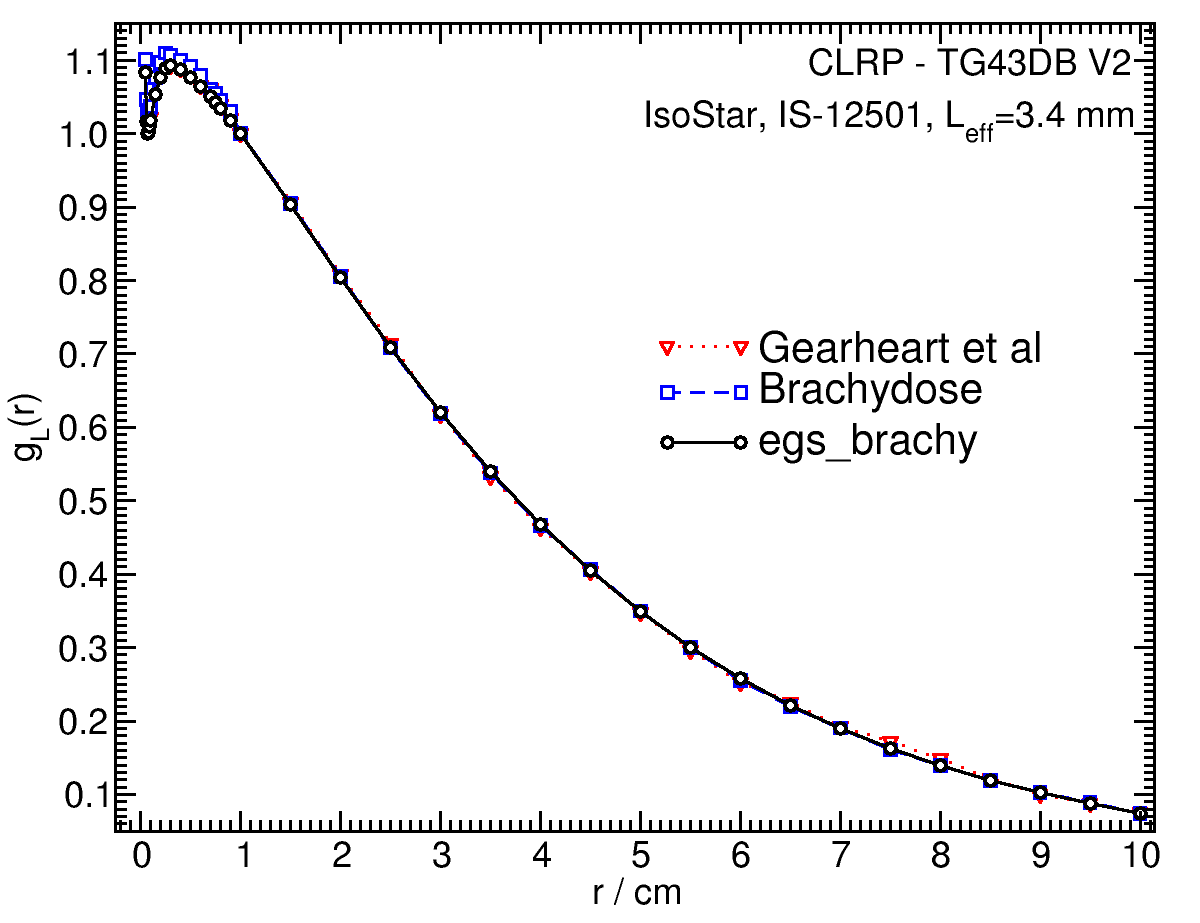
Radial dose function - g(r):
The radial dose function, g(r), is calculated using both line and point source geometry functions and tabulated at 36 different radial distances ranging from 0.05 cm to 10 cm. Fit parameters for a modified polynomial expression are also provided 11 . The mean residual deviations from the actual data for the best fit were < 0.16%.
| Fitting coefficients for g L (r) = (a0 r-2 + a1 r-1 + a2 + a3r + a4r2 + a5 r3) e-a6r | |||
| Fit range | Coefficients | ||
| r min (cm) | r max (cm) | ||
| 0.05 | 10.0 | a0 / cm2 | (1.088+/-0.023)E-03 |
| a1 / cm | (-2.87+/-0.04)E-02 | ||
| a2 | (1.2059+/-0.0019)E+00 | ||
| a3 / cm-1 | (3.89+/-0.04)E-01 | ||
| a4 / cm-2 | (-3.98+/-0.27)E-03 | ||
| a5 / cm-3 | (1.95+/-0.07)E-03 | ||
| a6 / cm-1 | (4.491+/-0.020)E-01 | ||
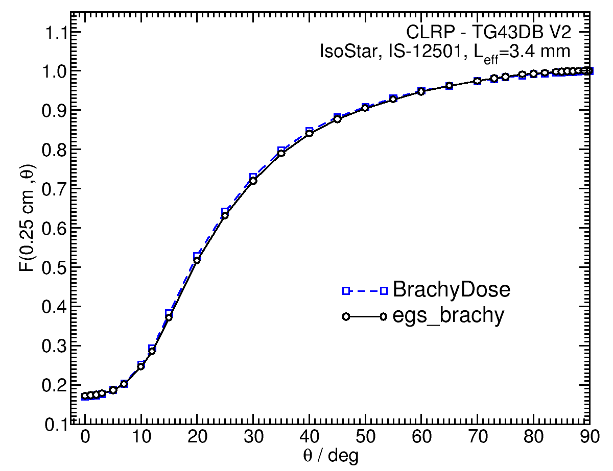
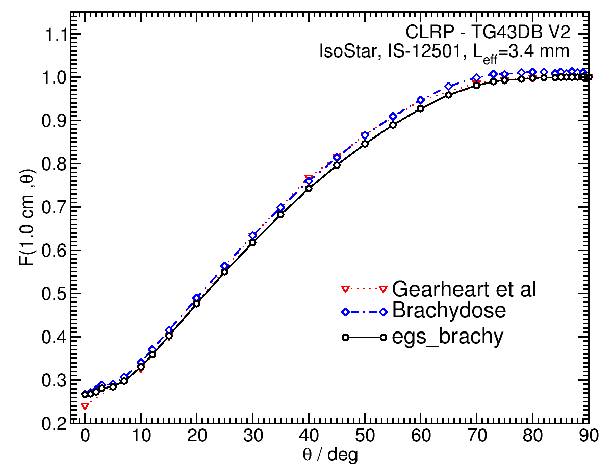
Anisotropy function - F(r,θ):
Anisotropy functions are calculated using the line source approximation and tabulated at radii of 0.1, 0.15, 0.25, 0.5, 0.75, 1, 2, 3, 4, 5, 7.5 and 10 cm and 32 unique polar angles with a minimum resolution of 5 o . The anisotropy factor, φ an (r), was calculated by integrating the solid angle weighted dose rate over 0 o ≤ ϑ ≤ 90 o .
|
F(0.25,θ) F(5.00,θ) |
F(1.00,θ) |
Tabulated data:
Tabulated data are available in .xlsx format: Excel
References:
1. D. M. Gearheart et al , Dosimetric characteristics of a new 125I brachytherapy source, Med. Phys., 27 , 2278 - 2285, 2000
2. R. Nath, N. Yue, Dose distribution along the transverse axis of a new 125I source for interstitial brachytherapy, Med. Phys., 27 , 2536 - 2540, 2000
3. G. S. Ibbott, R. Nath, Dose-rate constant for Imagyn 125I brachytherapy source, Med. Phys., 28 , 705, 2001
4. G. S. Ibbott, Monte Carlo determination of dose rate constant, Med. Phys., 29 , 1637 - 1638, 2002
5. R. E. P. Taylor et al , Benchmarking BrachyDose: voxel-based EGSnrc Monte Carlo calculations of TG-43 dosimetry parameters, Med. Phys., 34 , 445 - 457, 2007
6. R. Loevinger, Wide-angle free-air chamber for calibration of low-energy brachytherapy sources, Med. Phys., 20 , 907, 1993
7. S. M Seltzer et al , New National Air-Kerma-Strength Standards for 125I and 103Pd Brachytherapy Seeds, J. Res. Natl. Inst. Stand. Technol., 108 , 337 - 358, 2003
8. H. Safigholi, M. J. P. Chamberland, R. E. P. Taylor, C. H. Allen, M. P. Martinov, D. W. O. Rogers, and R. M. Thomson, Update of the CLRP TG-43 parameter database for LDR brachytherapy sources, to be published (Current calculation).
9. M. Rodriguez , D. W. O. Rogers, Effect of improved TLD dosimetry on the determination of dose rate constants for 125I and 103Pd brachytherapyseeds, Med.Phys. 41, 114301-15, 2014
10. M. J. Rivard et al , Update of AAPM Task Group No. 43 Report: A revised AAPM protocol for brachytherapy dose calculations, Med. Phys., 31 , 633 - 674, 2004
11. R. E. P. Taylor, D. W. O. Rogers, More accurate fitting of 125I and 103Pd radial dose functions, Med. Phys., 35 , 4242-4250, 2008