
Source Description:
Dimensions for the I-Plant seed are taken from the TG43U1S1 1 report by Rivard et al. (Note: The CLRPv1 database took the source dimensions from another Rivard study 2). The I-Plant seed has a Ti capsule with an outside diameter of 0.80 mm and end welds which are 0.25 mm thick cylindrical sections. (Note: In CLRPv1 database the Ti capsule outside diameter was 0.836 mm and end welds were 0.330 mm thick sphere). The wall thickness of the Ti capsule is 0.05 mm (Note: CLRPv1 database value: 0.0558 mm). Inside the source there is an Ag marker assumed to have a total length of 3.76 mm (Note: CLRPv1 database value: 3.60 mm) and a radius of 0.203 mm. The length of each conical end marker is 0.65 mm and has a half-angle of approximately 17.34 o (Note: CLRPv1 database value: 18.2 o). The active element of the source is a quartz tube surrounding the marker that is 3.76 mm in length and has inside and outside diameters of 0.4318 mm and 0.635 mm, respectively. The quartz tube is covered in a 16.0 μm thick active layer of Si containing 124 Xe which is in turn covered by a 5.0 μm thick layer of Si0 2 . The active layer is assumed to have a density of 2.58 g/cm3 and is composed of 97.6% Si, 2.38% Xe, 1.60x10⁻³ % I and 6.00x10⁻⁴ % Te. The overall length is 4.60 mm (Note: CLRPv1 database value: 4.50 mm) and the active length is 3.76 mm. The cylindrical source element is free to move approximately 0.12 mm along the seed axis and 0.024 mm radially from the center of the seed (Note: Previous database values were 0.090 mm and 0.056 mm, respectively), however, we assume it is always centred. The mean photon energy calculated on the surface of the source is 28.12 keV with statistical uncertainties < 0.02%.
(Note: The mean photon energy of this seed in the CLRP_TG43v2 paper 6 (Table II, seed # 9) was mistakenly reported as 28.30 keV while the correct value is 28.12 keV, as reported here.)
(Note: As we used the TG43U1S1 1 recommended source geometry for this CLRP update rather than Rivard et al 2 values which were used in CLRPv1, 2D anisotropy results showd mean deveations of about 5% at r ≤ 0.5 cm and angles below 10 °relative to CLRPv1).
Dose-Rate Constant - Λ :
Dose-rate constants, Λ , are calculated by dividing the dose to water per history in a (0.1 mm)3 voxel centered on the reference position, (1 cm,Π/2), in a 30x30x30 cm3 water phantom, by the air-kerma strength per history (scored in vacuo). As described in ref. 3 , dose-rate constants are provided for air-kerma strength calculated using voxels of 2.66x2.66x0.05 cm3 (WAFAC) and 0.1x0.1x0.05 cm3 (point) located 10 cm from the source. The larger voxel size averages the air kerma per history over a region covering roughly the same solid angle subtended by the primary collimator of the WAFAC 4, 5 at NIST used for calibrating low-energy brachytherapy sources and is likely the most clinically relevant value. The small voxel serves to estimate the air kerma per history at a point on the transverse axis and includes a small 1/r2 correction (0.5%)3. MC uncertainties are only statistical uncertainties (k=1).
Note: Results from Taylor and Rogers for this seed mistakenly included a cylindrical shell of water around the seed in air-kerma calculations. This increased their DRC value. Also, since radioactive materials are far away from silver marker, the average energy and DRC value are higher rather other silver marker sources.
| Author | Method | Λ (cGy h-1 U-1) | Abs. Uncertainty |
| Safigholi et al 6 | WAFAC | 0.9820 | 0.0001 |
| Safigholi et al 6 | point | 0.9796 | 0.0019 |
| Taylor, Rogers 7 | WAFAC | 0.994 | 0.002 |
| Taylor, Rogers 7 | point | 0.998 | 0.003 |
| Rivard 2 | extrap. (MCNP) | 1.017 | 0.005 |
| Wallace 8 | TLD | 1.01 | 0.04 |
| Duggan, Johnson 9 | TLD | 1.01 | N/A |
| Rodriguez, Rogers 10 | TLD Revised (Wallace) | 0.983 | 0.041 |
| Rodriguez, Rogers 10 | WAFAC (BrachyDose) | 0.987 | 0.015 |
| Rivard et al 1 | TG43U1S1 Consensus Value | 1.014 |
Radial dose function - g(r):
The radial dose function, g(r), is calculated using both line and point source geometry functions and tabulated at 36 different radial distances ranging from 0.05 cm to 10 cm. Fit parameters for a modified polynomial expression are also provided 11. The mean residual deviations from the actual data for the best fit were < 0.06%.
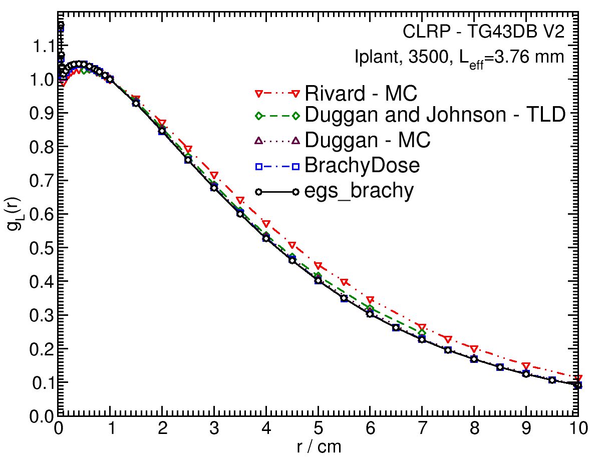
| Fitting coefficients for g L (r) = (a0 r-2 + a1 r-1 + a2 + a3r + a4r2 + a5 r3) e-a6r | |||
| Fit range | Coefficients | ||
| r min (cm) | r max (cm) | ||
| 0.05 | 10.0 | a0 / cm2 | (3.850+/-0.017)E-04 |
| a1 / cm | (-1.329+/-0.006)E-02 | ||
| a2 | (1.1519+/-0.0005)E+00 | ||
| a3 / cm-1 | (4.37+/-0.04)E-01 | ||
| a4 / cm-2 | (-7.0+/-0.7)E-03 | ||
| a5 / cm-3 | (2.45+/-0.09)E-03 | ||
| a6 / cm-1 | (4.544+/-0.028)E-01 | ||
Anisotropy function - F(r,θ):
Anisotropy functions are calculated using the line source approximation and tabulated at radii of 0.1, 0.15, 0.25, 0.5, 0.75, 1, 2, 3, 4, 5, 7.5 and 10 cm and 32 unique polar angles with a minimum resolution of 5 o . The anisotropy factor, φ an (r), was calculated by integrating the solid angle weighted dose rate over 0 o ≤ ϑ ≤ 90 o .
F(0.25,θ)  |
F(0.50,θ) 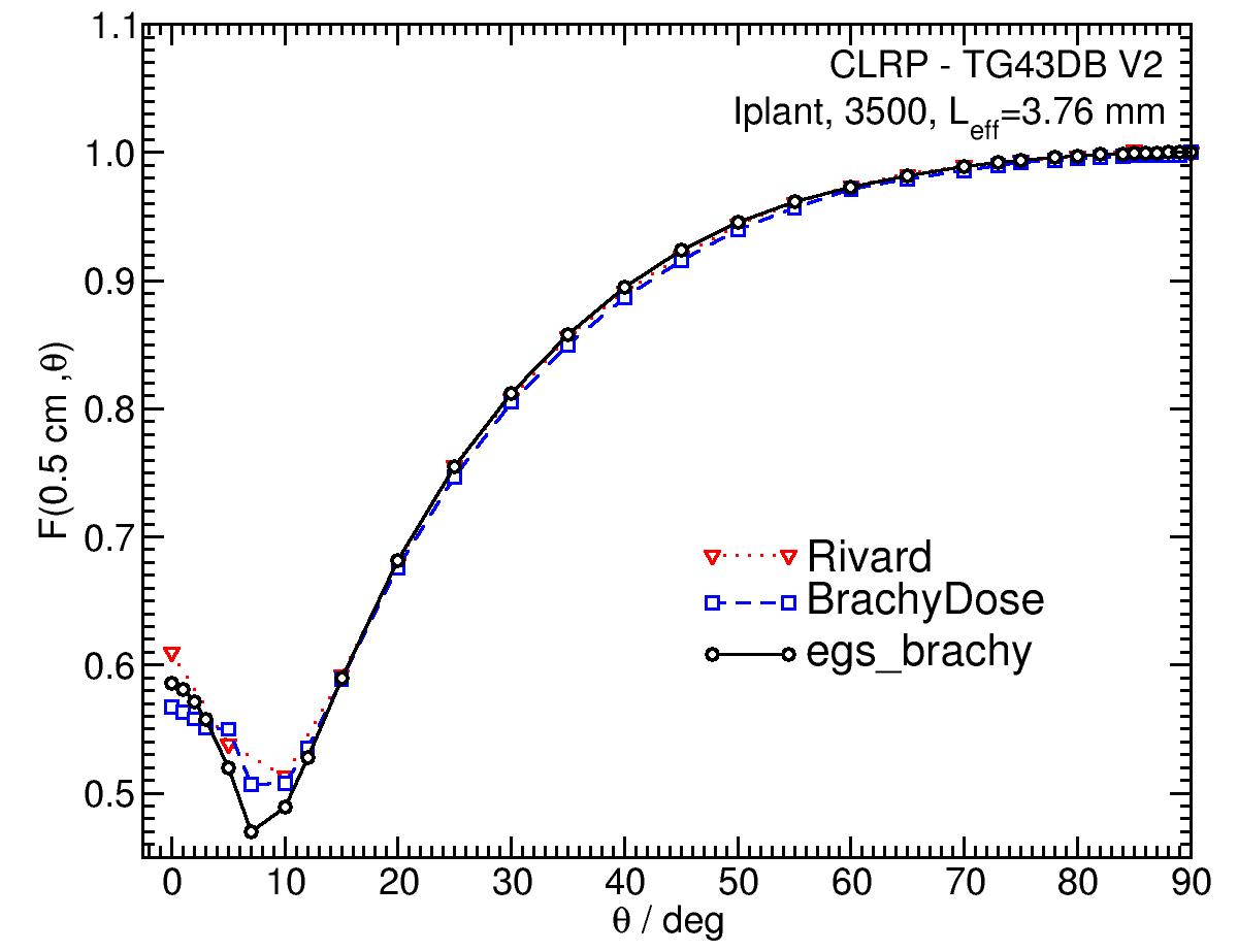 |
F(1.00,θ) 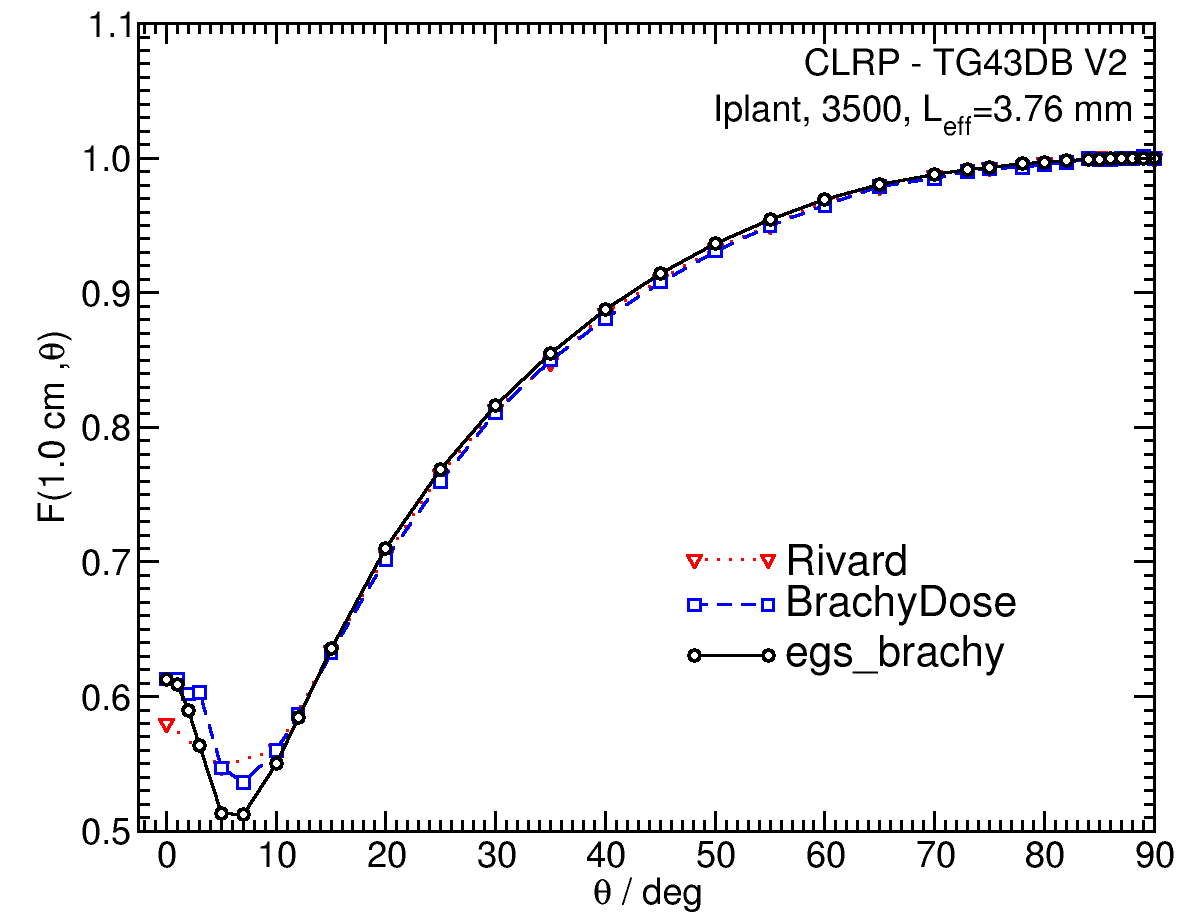 |
F(5.00,θ) 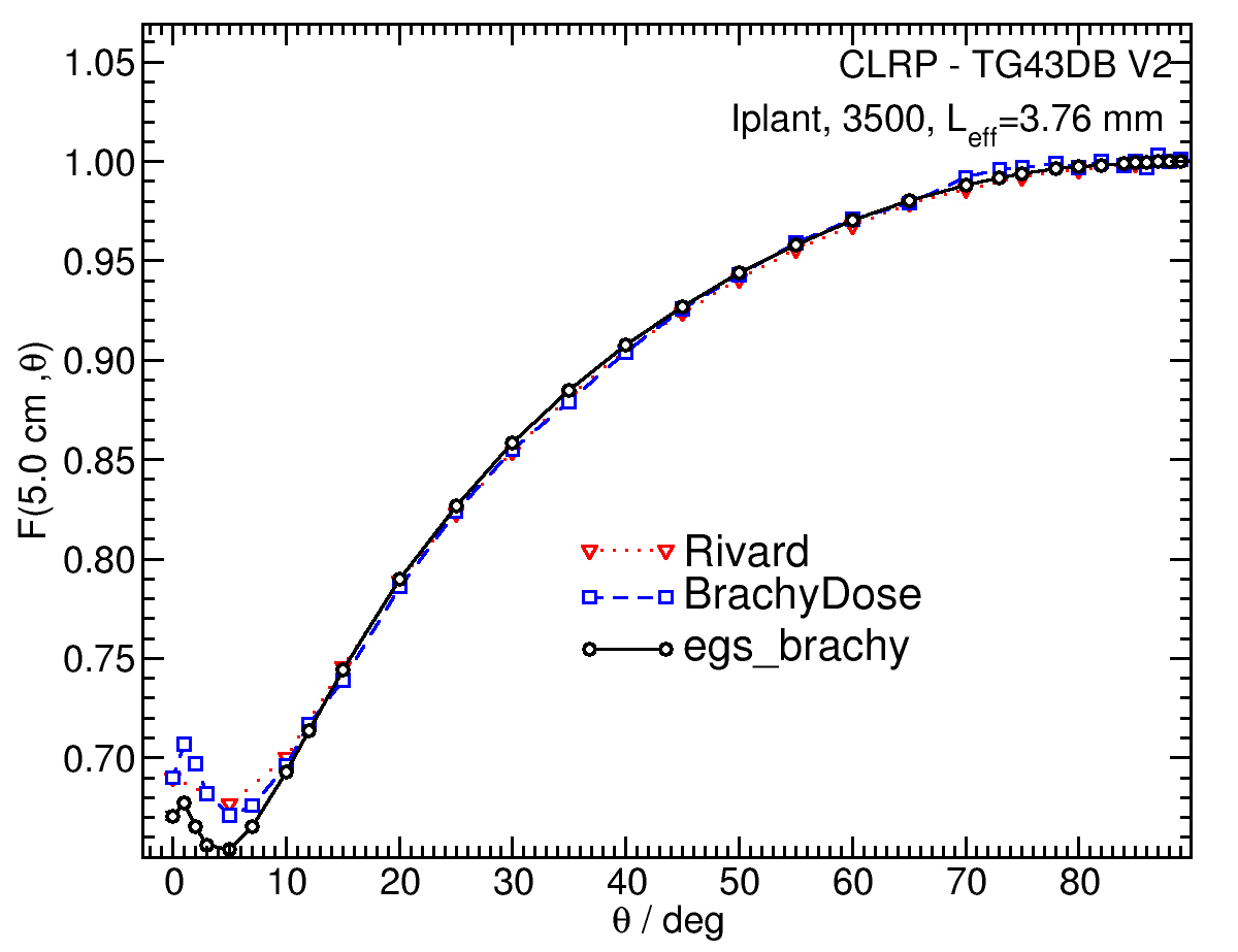 |
Tabulated data:
Tabulated data are available in .xlsx format: Excel
References:
1. M. J. Rivard et al , Supplement to the 2004 update of the AAPM Task Group No. 43 Report, Med. Phys., 34 , 2187 - 2205, 2007
2. M. J. Rivard, Comprehensive Monte Carlo calculations of AAPM Task Group Report No. 43 dosimetry parameters for the Model 3500 I-Plant 125I brachytherapy source, Appl. Radiat. Isotopes, 57 , 381- 389, 2002
3. R. E. P. Taylor et al , Benchmarking BrachyDose: voxel-based EGSnrc Monte Carlo calculations of TG-43 dosimetry parameters, Med. Phys., 34 , 445 - 457, 2007
4. R. Loevinger, Wide-angle free-air chamber for calibration of low-energy brachytherapy sources, Med. Phys., 20 , 907, 1993
5. S. M Seltzer et al , New National Air-Kerma-Strength Standards for 125 I and 103 Pd Brachytherapy Seeds, J. Res. Natl. Inst. Stand. Technol., 108 , 337 - 358, 2003
6. H. Safigholi, M. J. P. Chamberland, R. E. P. Taylor, C. H. Allen, M. P. Martinov, D. W. O. Rogers, and R. M. Thomson, Update of the CLRP TG-43 parameter database for LDR brachytherapy sources, to be published (Current calculation).
7. R. E. P. Taylor, D. W. O. Rogers, An EGSnrc Monte Carlo-calculated database of TG-43 parameters, Med. Phys., 35 , 4228--4241, 2008
8. E. Wallace, Model 3500 125I brachytherapy source dosimetric characterization, Appl. Radiat. Isotopes, 56 , 58-587, 2001
9. D. Duggan, B. L. Johnson, Dosimetry of the I-Plant Model 3500 iodine-125 brachytherapy source, Med. Phys., 28 , 661-670, 2001 10. M. Rodriguez , D. W. O. Rogers, Effect of improved TLD dosimetry on the determination of dose rate constants for 125I and 103Pd brachytherapyseeds, Med.Phys. 41, 114301-15, 2014.
11. R. E. P. Taylor, D. W. O. Rogers, More accurate fitting of 125I and 103Pd radial dose functions, Med. Phys., 35 , 4242-4250, 2008
Carleton Laboratory for Radiotherapy Physics
CLRP TG-43 Parameter Database V2
May 5, 2020